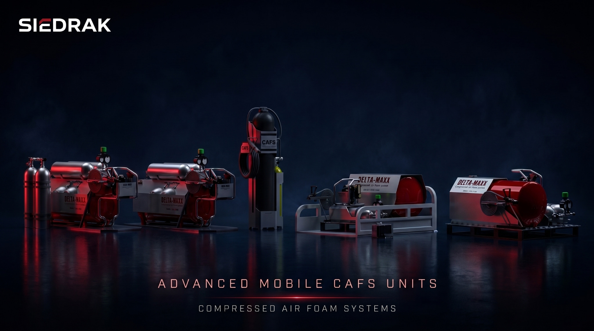
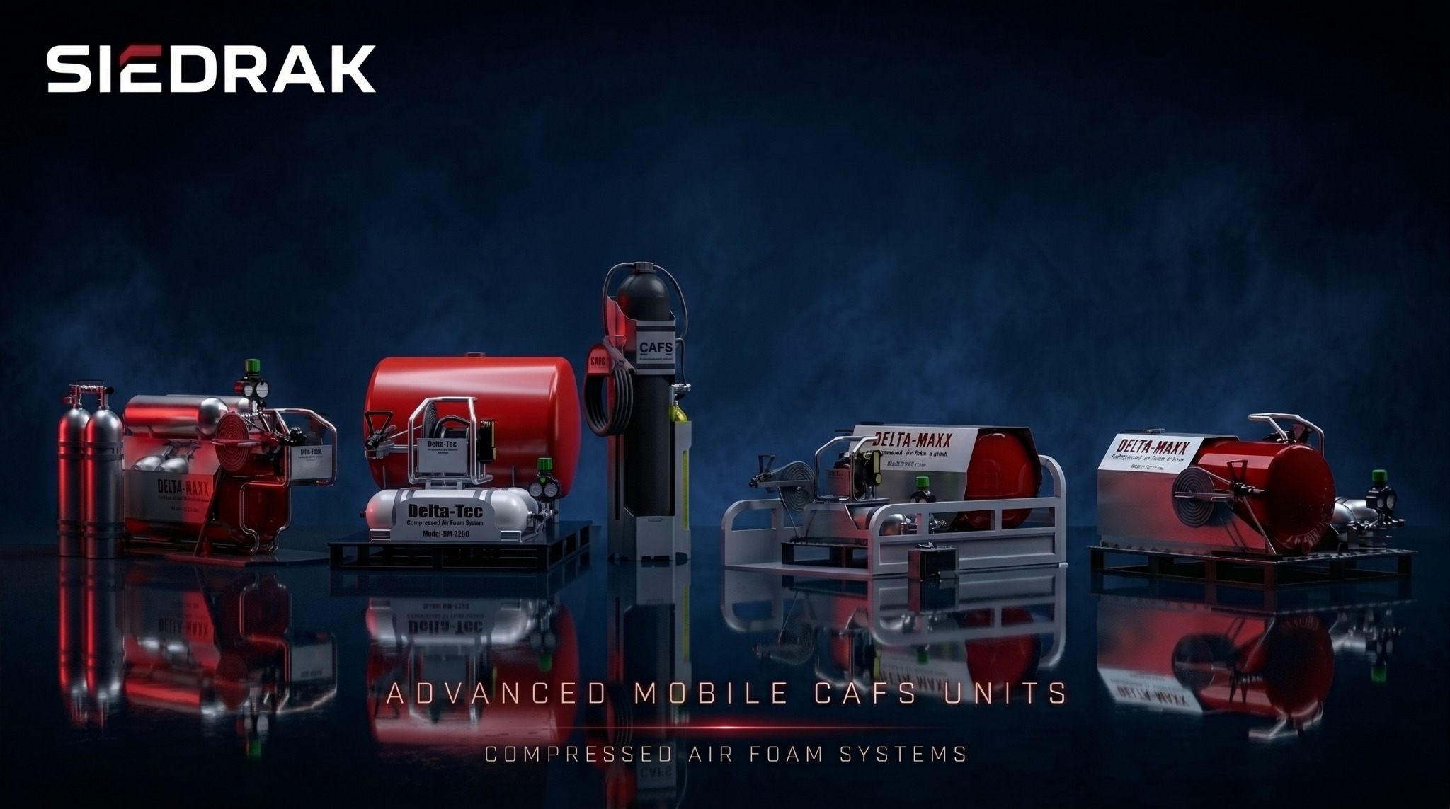
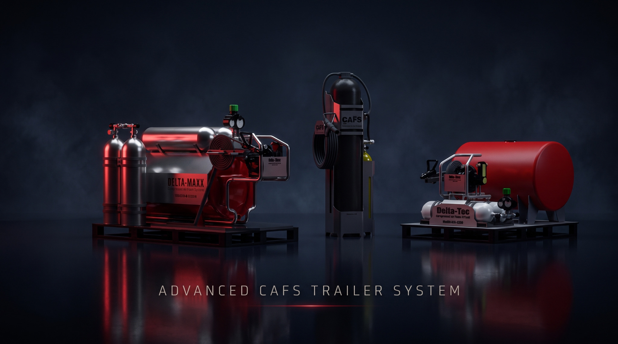
CAFS unit family overview

01 Engineering case study

Advanced Mobile
CAFS Units

Compressed Air Foam Systems / Mechanical & Mechatronic Product Engineering

A modular family of mobile and skid-mounted CAFS units engineered around compact packaging, pressure-system integration, structural support, and practical field deployment.

Mechanical Design3D CADEquipment PackagingSkid DesignDFM

02 Project overview

A coordinated
product family.

SIEDRAK developed a family of modular Compressed Air Foam System concepts integrating pressure equipment, liquid storage, hose management, dispensing hardware, structural frames, and operator-access features into compact, transportable product architectures.

Multiple configurations were explored to address different capacity, footprint, protection, and deployment requirements. The work treats each unit as a mechanical and mechatronic product-development project, not simply an arrangement of components.

System principleWater + foam concentrate + compressed air

CAFS introduces compressed air into the foam solution before discharge. A functional package therefore requires coordinated integration of storage, pressure control, valves, gauges, piping, hose management, dispensing hardware, structural frames, and operator interfaces.

04 Project challenge

Compact, stable,
serviceable.

The central challenge was to package several mechanical and fluid-system components into a compact, stable, serviceable, and transportable architecture.

Components had to remain accessible while pressure hardware stayed protected. Tanks and cylinders required stable support, major masses needed a manageable footprint, and the final assembly had to read as one coherent engineered product.

Engineering objectives

  • 01Compact CAFS equipment layouts
  • 02Integrated tanks, cylinders, hose reels, pumps, regulators, gauges and valves
  • 03Structurally robust skid and frame systems
  • 04Practical service and operator access
  • 05Protected exposed equipment
  • 06Improved portability and transportability
  • 07Stable pressure-vessel and tank mounting
  • 08Controlled hose and piping routing
  • 09Minimal overall footprint
  • 10Modular architecture for several configurations
  • 11Coherent industrial product language
  • 12A foundation for fabrication and DFM development

05 System architecture

Engineered as a
coordinated assembly.

Every subsystem is positioned in relation to structure, access, protection, operator use, and the equipment around it.

01

Main liquid / foam storage

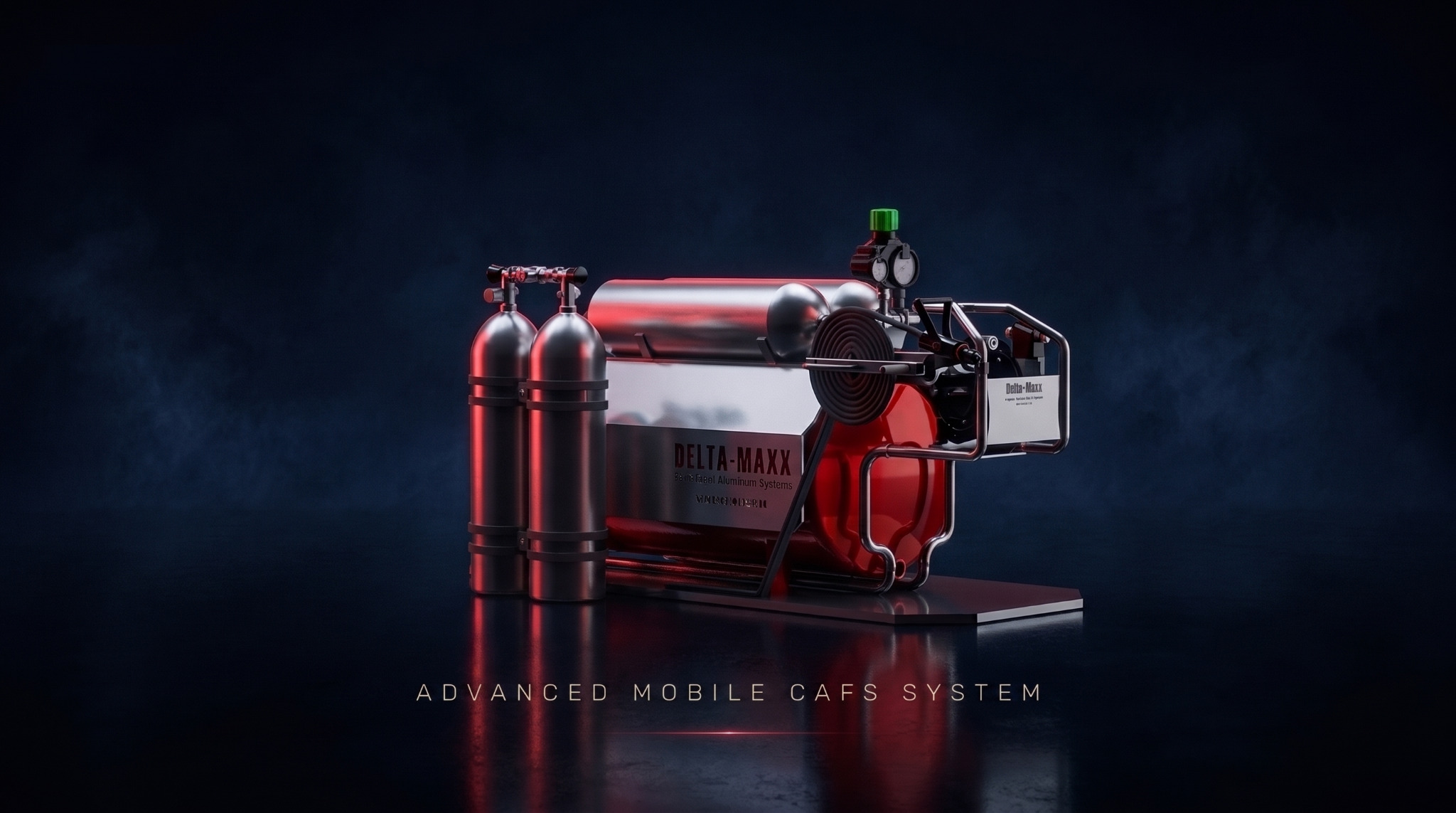
The primary tank is a major reference component for packaging, weight distribution, structural frame design, equipment access, and overall system dimensions. The surrounding assembly is organized around stable support and practical connection access.
02

Compressed-air storage / supply

Dedicated cylinders and compressed-air hardware require secure retention, impact protection, accessible valve positions, supported mounting, and clearance around regulators and fittings. Vertical cylinder arrangements were explored to reduce footprint while preserving access.

03

Pressure regulation & instrumentation

Regulators, gauges, control valves, manifolds, and fittings are positioned where operators can inspect and adjust them. Protective geometry is coordinated with clear access to the primary pressure-control hardware.

04

Hose management

Integrated hose reels organize storage and deployment while limiting interference with adjacent components. Reel supports are considered as structural elements that must react the loads created during hose deployment and retrieval.

05

Pump / dispensing module

The pump and dispensing assembly is packaged within a protective tubular frame to improve handling, protect components, define mounting points, and simplify service removal.

06

Structural skid

The skid is the mechanical foundation for tanks, cylinders, pumps, hose reels, guards, pressure equipment, and accessories. It also creates clear interfaces for transport, installation, securing, and possible vehicle or trailer integration.

07

Protective structures

External frames and cages define service zones, add impact protection, improve handling, and create stronger mounting interfaces for demanding industrial or emergency-response environments.

06 Design variants

Different packaging.
Shared engineering logic.

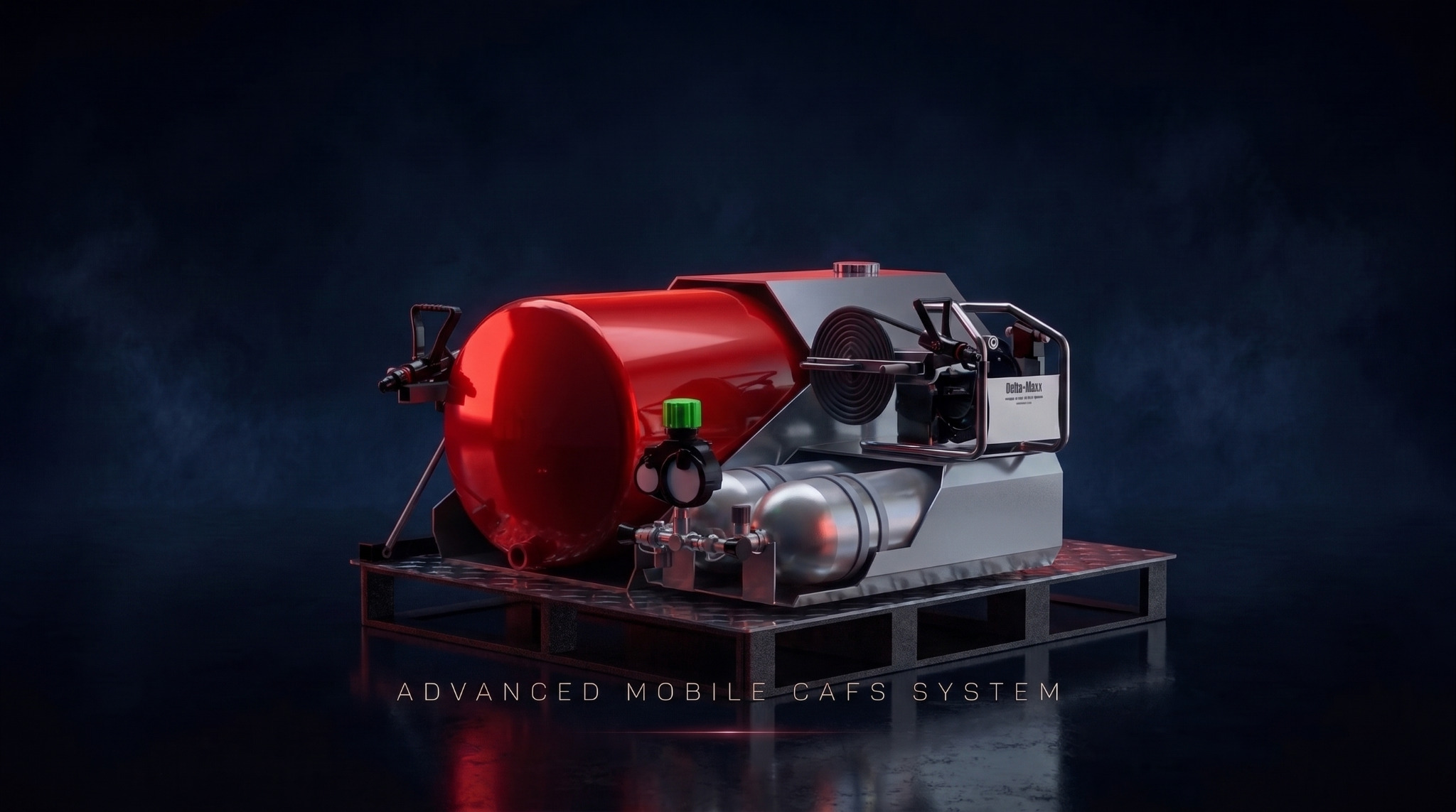
01 / Concept

Compact twin-cylinder CAFS skid

The horizontal equipment module integrates twin compressed-air cylinders, primary storage, pressure-control hardware, gauges, a hose reel, dispensing hardware, tubular guards, and a compact skid base.

Design intention

A compact, self-contained architecture where the main operating components remain visible and accessible within a relatively small footprint.

Compact twin-cylinder CAFS skid
04Compact twin-cylinder CAFS skid
Compact system integration detail
05Compact system integration detail
02 / Concept

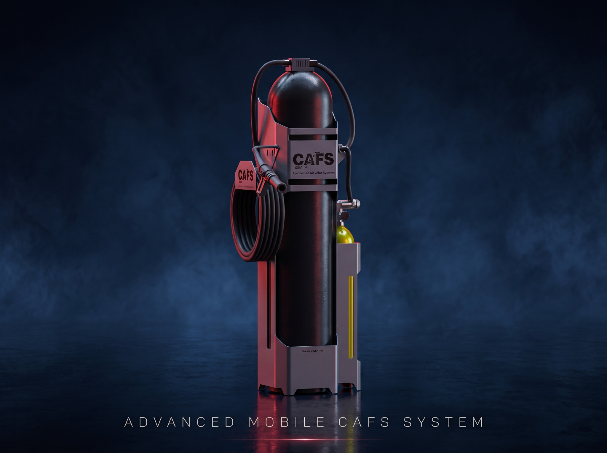
Vertical CAFS service unit

The tall primary cylinder, hose storage, dispensing hardware, equipment enclosure, auxiliary bottle location, and protective housing are organized vertically to reduce the required footprint.

Design intention

An alternative packaging strategy developed for installations where available floor area is limited.

Vertical CAFS service unit
06Vertical CAFS service unit
03 / Concept

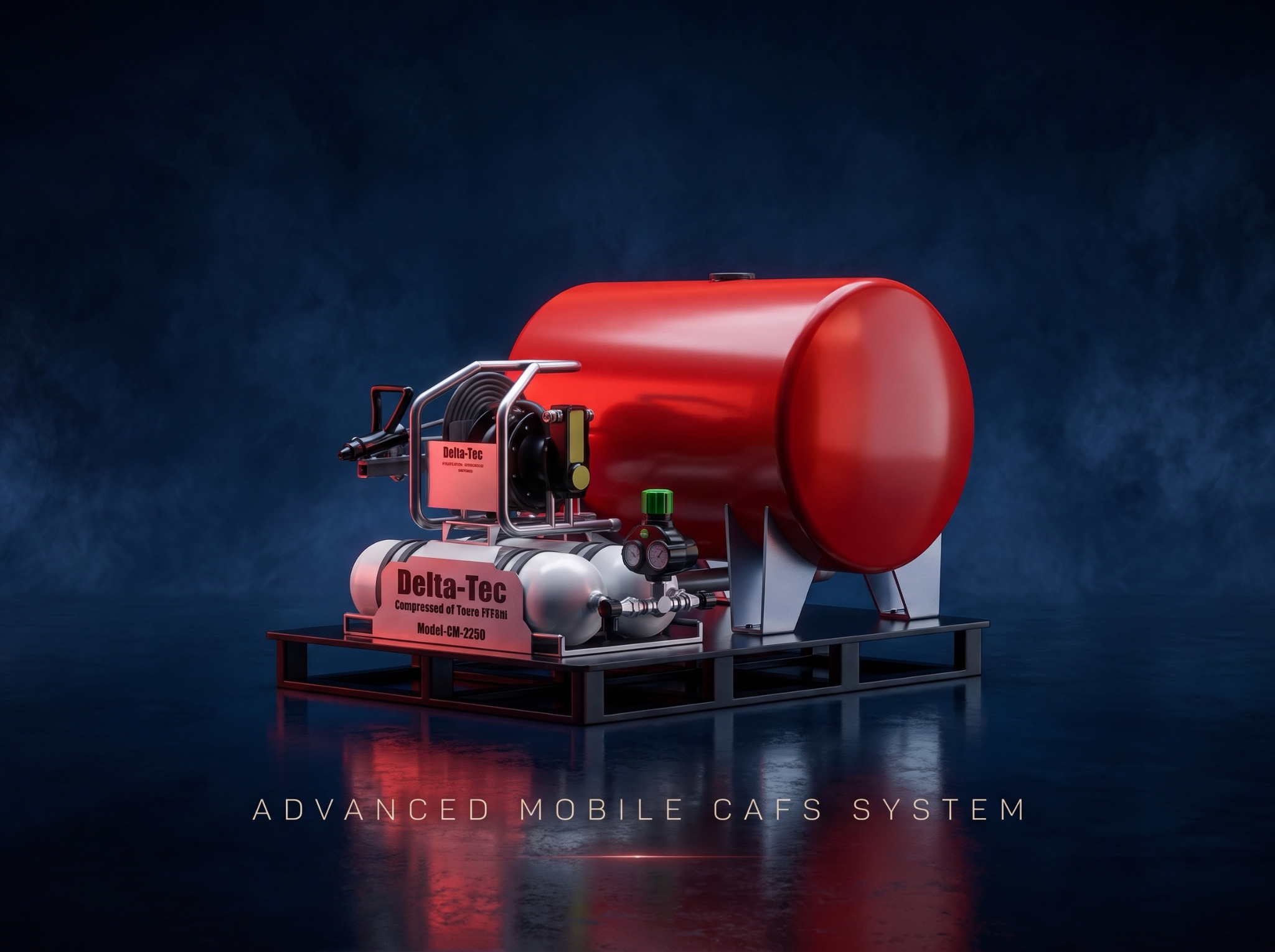
Integrated tank CAFS skid

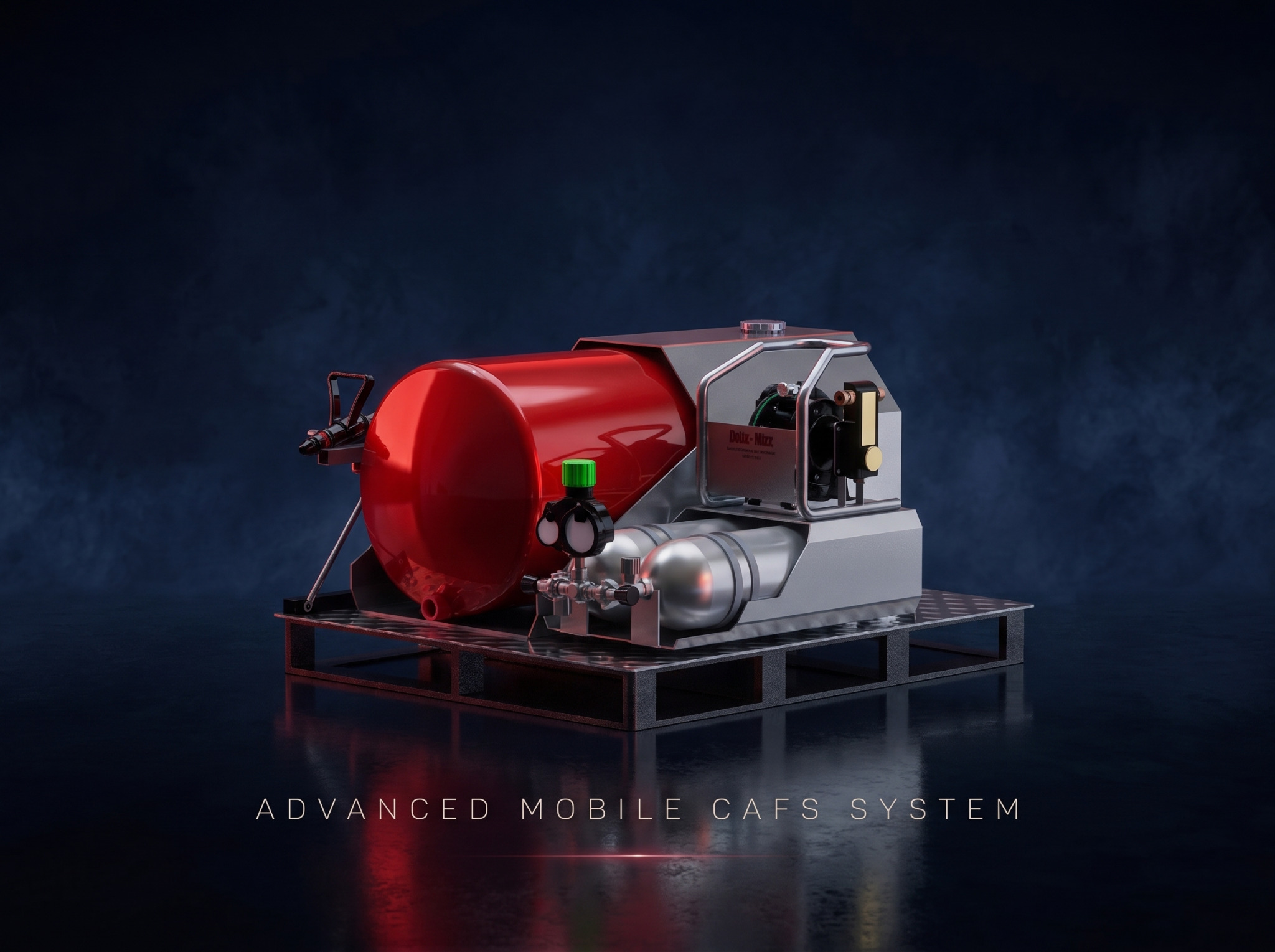
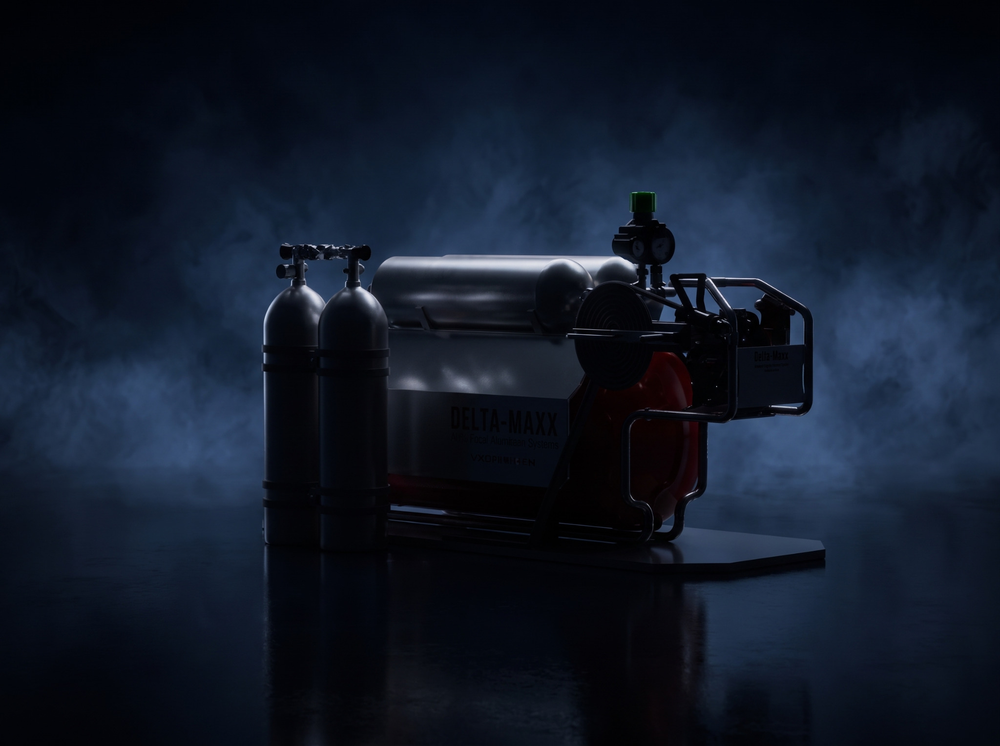
A large horizontal tank is coordinated with a secondary pressure vessel, regulator and gauge assembly, pump module, structural tank supports, and a fabricated skid base as one transportable assembly.

Design intention

A higher-capacity architecture that keeps the main equipment masses low while placing operating hardware toward the accessible side of the system.

Integrated large-tank CAFS skid
08Integrated large-tank CAFS skid
Large-tank skid-mounted CAFS unit
09Large-tank skid-mounted CAFS unit
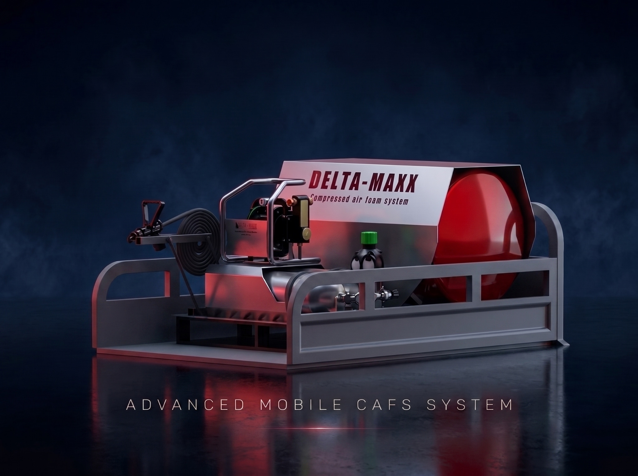
04 / Concept

Protected CAFS frame system

The integrated tank layout is surrounded by a larger protective structure that defines operator access, provides additional mounting surfaces, and visually unifies the complete assembly.

Design intention

A more industrialized architecture for handling, protection, and deployment in demanding operating conditions.

Protected CAFS frame system
10Protected CAFS frame system

07 Key features

Built for integration.
Shaped for use.

01

Modular architecture

Multiple configurations developed around one CAFS engineering philosophy.

02

Integrated pressure equipment

Packaging for cylinders, regulators, gauges, tanks, valves, and associated hardware.

03

Compact footprint

High component density without sacrificing critical access.

04

Serviceable design

Layouts organized around inspection, maintenance, and component replacement.

05

Structural skid systems

Integrated frames support tanks, pumps, cylinders, and operating hardware.

06

Field deployment

Architectures shaped by transport, handling, protection, and practical setup.

09 SIEDRAK role

Mechanical product
development & CAD.

The project established complete 3D assemblies and coordinated layouts as a foundation for detailed selection, validation, prototyping, DFM, and production documentation.

  • 01Concept development
  • 02Mechanical system architecture
  • 033D CAD modeling and assembly development
  • 04Equipment packaging
  • 05Structural frame design
  • 06Tank and cylinder mounting concepts
  • 07Component, hose, and equipment integration
  • 08Operator-access and serviceability studies
  • 09Product visualization and presentation rendering

Potential applications

Firefighting equipmentEmergency responseIndustrial fire protectionRemote facilitiesMobile response unitsUtility and service vehiclesTrailer-mounted systemsFacility protection systemsTemporary or remote deployment

Final technical specifications are configuration-dependent. No pressure rating, capacity, flow rate, certification, compliance approval, or performance claim is stated without verified engineering data.

10 Project outcome

A coherent platform
for future development.

The project resulted in a family of visually and mechanically coordinated CAFS equipment architectures capable of supporting different capacity, packaging, protection, and deployment requirements.

The concepts demonstrate how tanks, hoses, regulators, pumps, pressure equipment, and structural frames can become a coherent engineered product platform. The work provides a foundation for detailed component selection, fluid-system definition, structural validation, prototype fabrication, testing, DFM refinement, and production documentation.

Start a project